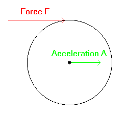
Figure 2.4)
The CM of a solid body, or system of bodies, is the weighted average, spatial distribution of all mass in the system.
For example, the CM of a symmetric object, such as a wheel, is at the center or axle.
For us, the most important fact regarding the center of mass is that a force applied to any part of the body will cause a parallel acceleration at the center of mass. For example, a force applied to a wheel somewhere along its radius, in the plane of the wheel, will cause acceleration at the axle parallel to the force. For a wheel in free space, this means that the wheel will start translating in the direction of the external force, as well as rotating. Figure 2.4) shows this situation.
Figure 2.4)
To get an idea of how this might be applied, consider the following question, which I call The Pole and Wheel:
A pole is attached to the ground via a hinge with negligible friction. A wheel of mass m is attached to the top of the pole via an axle that also has no significant friction. A rope of negligible mass is wound around the wheel's circumference with the end hanging toward the ground on the right hand side of the wheel. All of this is balanced at equilibrium, with the pole pointing vertically from the ground (what we have here is really just the rear of a mono-pivot attached to the ground).
How should you pull on the rope, in order that the pole will not fall? Should you pull vertically; left or right of vertical? Should you pull through the pivot?
Answer:
You should pull vertically, to the extent that one may assume the mass of the earth to be effectively infinite. To be precise, one should pull almost vertically, but juuuuust slightly to the left of vertical for the pole not to fall, since the mass of the earth is not truly infinite (for those interested in why the line is not exactly vertical, consider conservation of angular momentum).
Pull left of vertical and the pole will fall left, and analogously for the right (assuming the mass of the earth to be infinite). Pull through the pivot in particular and the pole will fall left. Figure 2.5) diagrams the situation.

Figure 2.5)
The key is to realize that the tension in the rope induces a force at the edge of the wheel, which in turn will induce a parallel force at the axle, just as theory predicts. The result follows.
One may look at this system as a mono-pivot bicycle with the earth as a giant front triangle.
Note: The Pole and Wheel question has been extremely difficult for most people. Even most physics professors do not get it right the first time, and none of the well-known bicycle suspension designers has realized this in the past. However, if one wishes to understand the forces present within a pedaled bicycle, this concept is essential.
If the reader is having difficulty with this issue, our suggestion is to conduct the experiment. A good way to do this is to take the front wheel holder from a Yakima (or other) car-mounted bike rack and remove all of the hardware. This is your pole. Attach a bike wheel and conduct the experiment. You will see that if the line of force at the wheel's edge goes though the bottom of the pole, then the pole and wheel will topple over. If the line of force at the wheel's edge is essentially vertical, then the pole and wheel will not topple over.
Those wishing a full presentation of the methods used here can find one in Classical Dynamics of Particles and Systems, by Marion, 1970. The center of mass equation of motion due to an external force is on page 68. The derivation starts on page 67.
In the previous example, we have considered a single force on the wheel, with the rotational inertia of the wheel opposing the external force. However, we may also consider multiple forces acting on the wheel. If there are at least two forces creating opposing torques on the wheel, about the axle, and the mass of the wheel is small compared to other quantities, then we may ignore the wheel mass. The simplest example is that of the Atwood machine in Figure 2.3 B). While the machine is in motion, we may take the tension T in the rope on each side to be equal, if we neglect the mass of the wheel. The force at the wheel axle is 2T; both force vectors external to the wheel pointing in the same direction. If the external forces on the wheel are not pointing in the same direction, the total force at the axle will be the vector sum.
Figure 2.6) shows the forces acting at the axle of a negligible mass wheel, which is experiencing multiple external forces at two different radii.
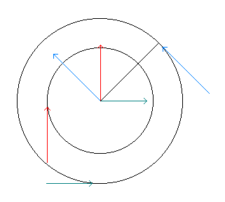
Figure 2.6)
Later, in Figure 2.12) of An Intuitive Look at Forces and Torques., we will consider an example of this, with the crank being an example of the wheel, and the pedal stroke from the rider and chain tension being the external forces. Those wishing to understand the calculations associated with Figure 2.12) should keep Figure 2.6 in mind.