Figure 2.13)
Read this section if:
You want a Path Analysis perspective on suspension tuning.
Skip this section if:
You are not interested.
This section is more difficult.
We don't want to spend too much time here, since this is probably the last issue about which a consumer should worry. All non-URT types can achieve all of the really useful suspension rates and most frames out there pair up fairly well with the stock shocks. Rate is only really a consideration for those who are real suspension wonks (yes, the author is a suspension wonk and if you are reading this, you are in danger of wonk-hood also) wanting to swap between coil and air shocks, which generally have different internal rates. Pairing a falling rate frame with a linear coil shock or an extremely rising rate frame with an air shock might not have acceptable results.
However, we do refer to suspension rate in other parts of this work, so we will look at the most important considerations.
All springs have rates and a suspension is just a type of spring.
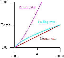
Define a coordinate x as the direction in which a spring compresses. The spring rate is a function of x, and describes the amount of force with which the spring will tend toward equilibrium at any point of compression or extension away from equilibrium. The steeper the rate function, the more a spring will resist additional movement the further it is moved from equilibrium. For a typical coil spring near equilibrium, the rate function is almost linear. If the rate function is concave up, then the spring has a rising rate; that is, the additional force needed to further compress the spring at each point will increase as the spring goes through its travel. If it is concave down, then the spring has a falling rate, with analogous results. Figure 2.13) shows a graph with each type of rate.
Figure 2.13)
The rate of a bicycle suspension is composed of the internal rate of the shock and the rate inherent in the suspension geometry.
Internal shock rates range from near linear to rising. Coil springs tend to have more linear rates, while air springs tend to have rising rates. All frames may be fitted with a range of shocks, which these days generally have one of two lengths and standard mounts. We will not consider shocks further, since they are not an inherent feature of frame geometry.
The contribution to rate from suspension geometry is determined by the way in which the shock mounts, front and rear wheel axles, and main triangle move relative to one another. The front wheel axle establishes frame orientation to the ground but generally may be neglected, since bottom brackets are almost universally 13" ± .5" from the ground without rider (given a typical assumption for the fork Crown to Axle Length or CAL). Thus, the rear wheel and BB largely determine the frame orientation to the ground.
Again, we don't want to spend too much time on this, so we will give an example of the contribution from the relative movement of the shock mounts. Similar consideration must be given to the rear wheel axle relative to the rear shock mount and BB.
Establishing the main triangle as our reference frame, the rear shock mount will travel a circular path around some pivot the main pivot in the case of a mono-pivot and the upper frame pivot in the case of a 4-bar (our following statements will apply in both cases).
If the tangent of the rear shock mount points near to the front shock mount as the suspension goes through its travel, then the relative movements of the shock mounts will have a neutral influence on suspension rate (by neutral we mean that, given a linear shock, the suspension rate will remain linear).
Figure 2.14) shows a suspension member moving in the frame of the main triangle. As the suspension compresses, if the rear mount tangent is moving into alignment with the front mount, then the path will increase the rise (decrease the fall) in rate. If it is moving out of alignment with the front mount, then the path will decrease the rise (increase the fall) in rate. This is because for a given angle of rotation, the two shock mounts move towards each other the most when the rear mount tangent is through the front mount.
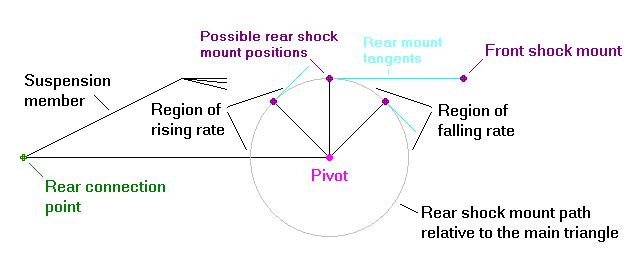
Figure 2.14)
Click to enlarge
If we are dealing with a mono-pivot, then the suspension member is the rear triangle and the rear connection will be to the rear axle. If we have a 4-bar, then the suspension member is the upper link and the rear connection will be to the rear link. In both cases, the larger the radius of the rear shock mount path, the larger will be the rate curvature due to geometry. Also, the longer the suspension member; the larger will be the magnification of the internal shock rate curvature, since the wheel will travel a greater distance for a given distance of rear shock travel.
This is most of the ballgame for a mono-pivot (minus only wheel path). For a 4-bar, one must do a similar analysis for the tangent of the upper rear pivot relative to the rear wheel axle. At any position in travel, if the tangent is pointing at the wheel axle, then the shock will compress least for a given amount of wheel travel. In most 4-bars this pivot has a path that will diminish the rate, and again, the larger the path radius of this pivot the larger will be the rate function curvature. The paths of the rear shock mount and upper rear pivot thus define the over all effect in a given 4-bar, minus wheel path.